|
|
The ABS system in the 1990 through 1993 Imperials was somewhat less than something worthy of being associated with the name "Imperial". The system was crude and primitive by today's standards and often failed, leaving the vehicle with no brake boost, and the perception of "no brakes" to many drivers, often resulting in serious front end colisions that would invariably spell the end of the vehicle. This says nothing about the doubtless property damage and human casualties that this poorly designed system has been responsible for over the last 10+ years.
Since the 90-93 Imperial is such a joy to drive, as any owner would attest, I decided to retrofit the failing ABS system in my Imperial, with the same old non-ABS style braking system that is found in the Imperial's sister cars, the New Yorker and Dynasty. Parts for this retrofit are affordable and readily available new, rebuilt or from a salvage yard.
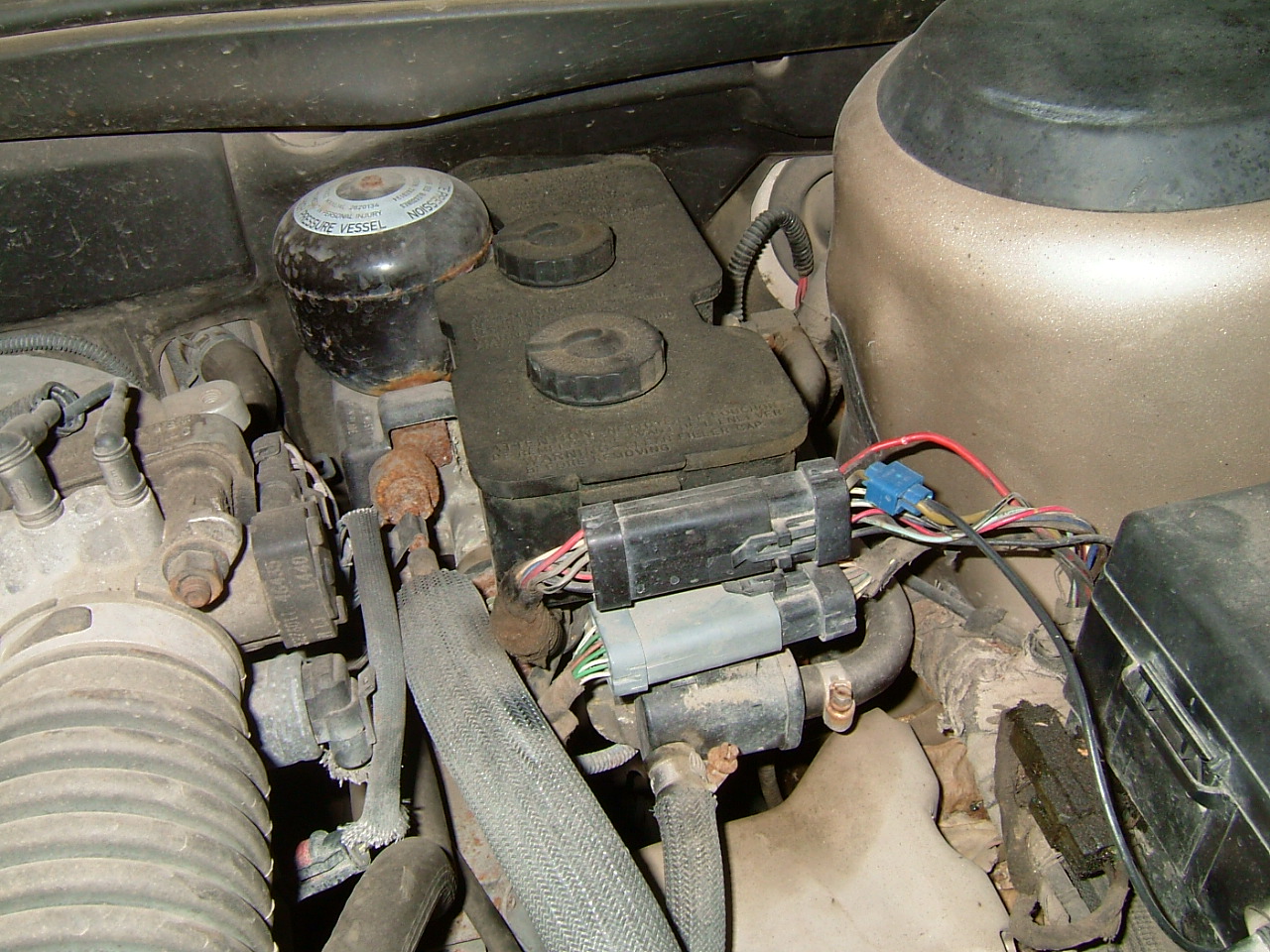
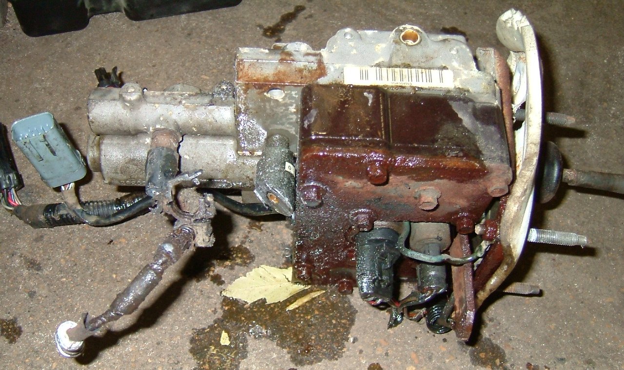
The project started by removing the massive ABS master cylinder and pump.

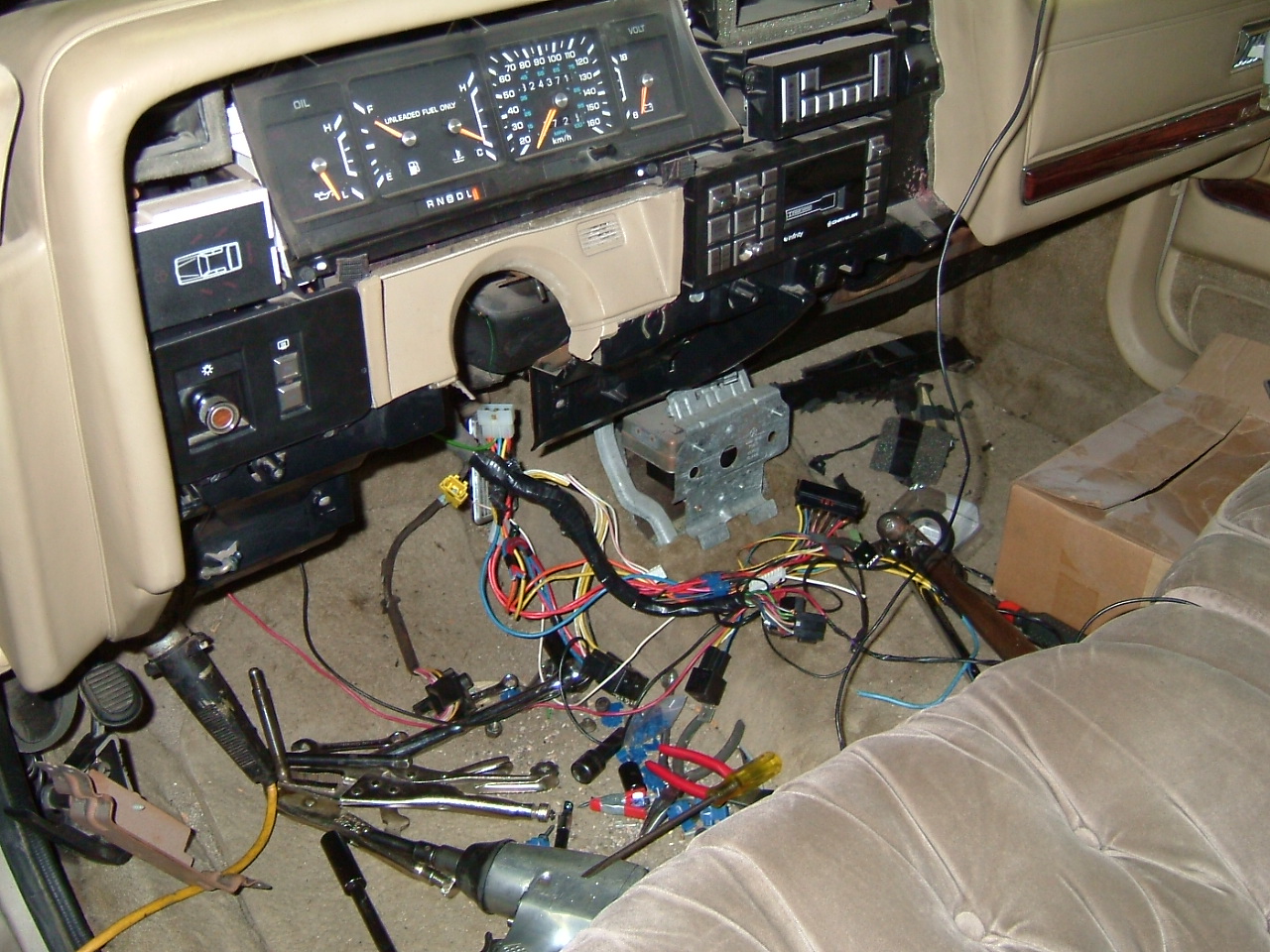
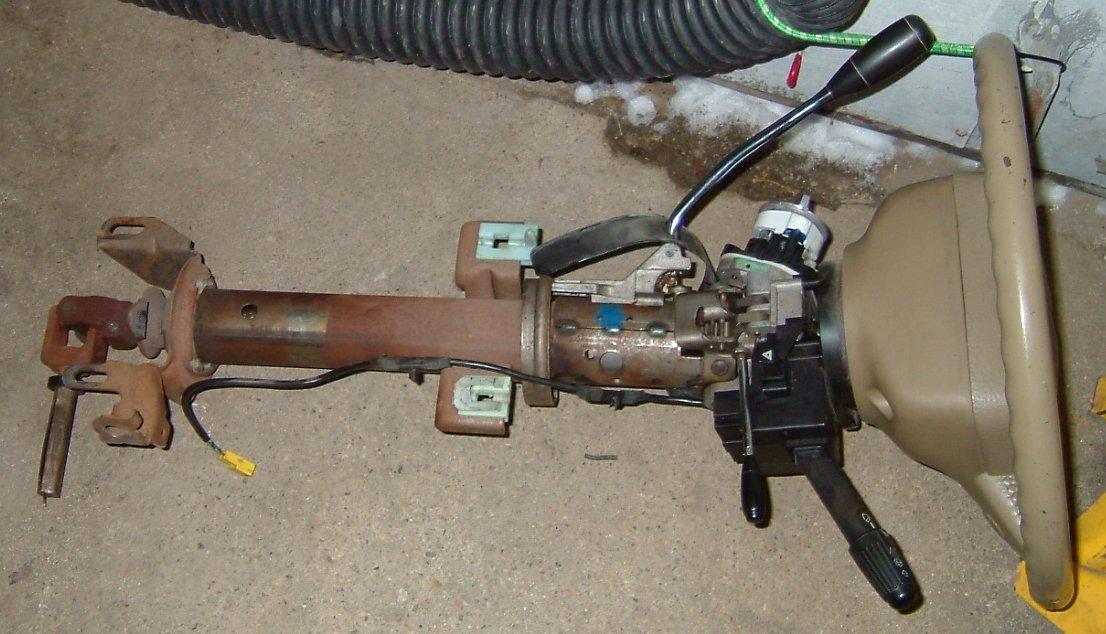
It may sound drastic but I found that removing the steering column is not very difficult and it affords far better access to the items under the dash that need to be changed. There are only four nuts that hold the column in. Before removing those however, remove the column covers and disconnect all the electrical conectors, don't forget the yellow air bag connector that is farther down the harness. The gear selector indicator is controled by a thin line that is attached to a metal bracket that goes around the column. Shift the car into N or D and then pull that little line up and out of the keeper. The gear selector linkage is a lever that connects to a rod lower on the column. The cable is held in place with a clip and the rod is attached with a plastic press-fit bushing. After everything is disconnected from the column and the four retaining nuts are out, the column can be coaxed out of the car. The steering shaft will slide out of the joint at the floor. Once the column is out, be very careful that you DO NOT TURN THE WHEEL more than a half revolution or so. There is a "clock spring" in the column that has all the electrical connections for the steering wheel controls and air bag. If you turn the wheel, you can permanently damage that mechanism and you'll be looking for a replacement column.
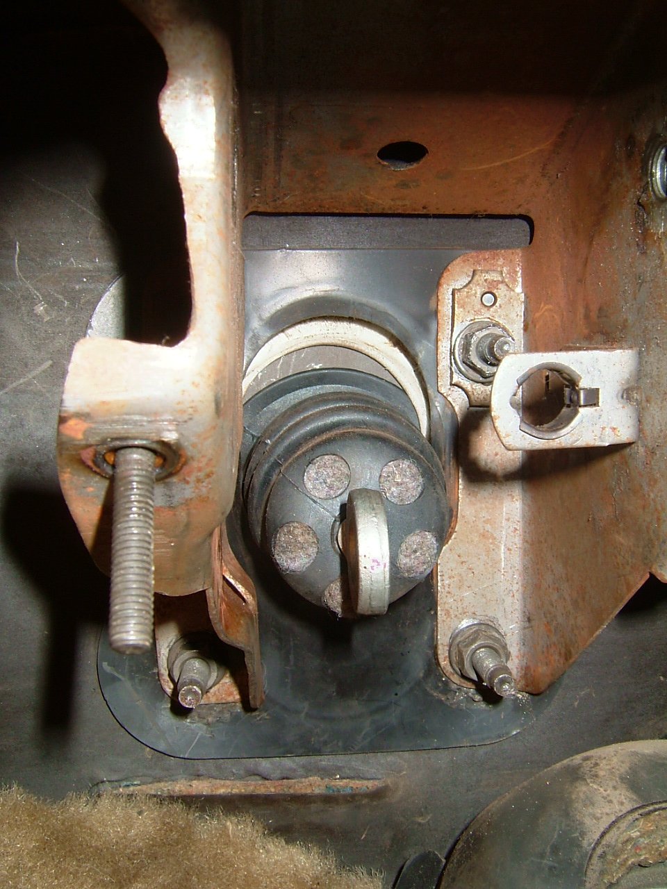
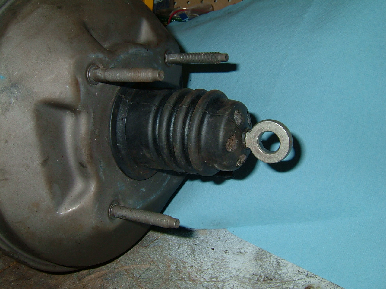
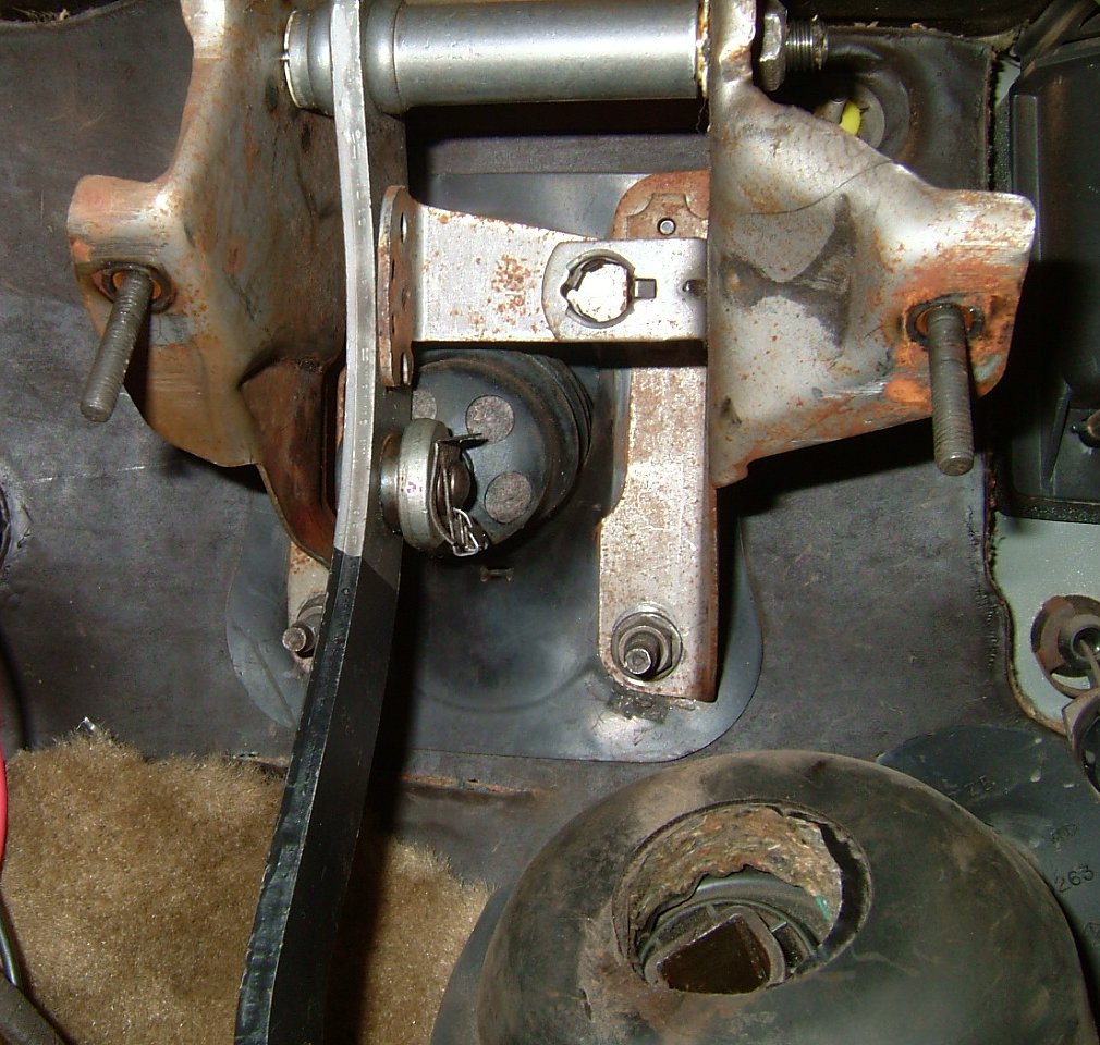
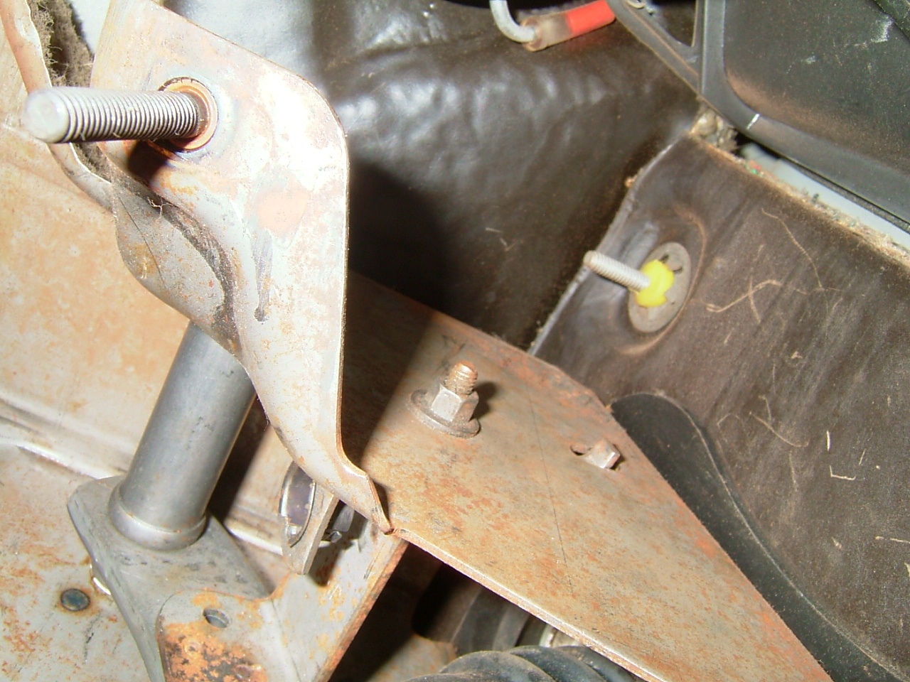
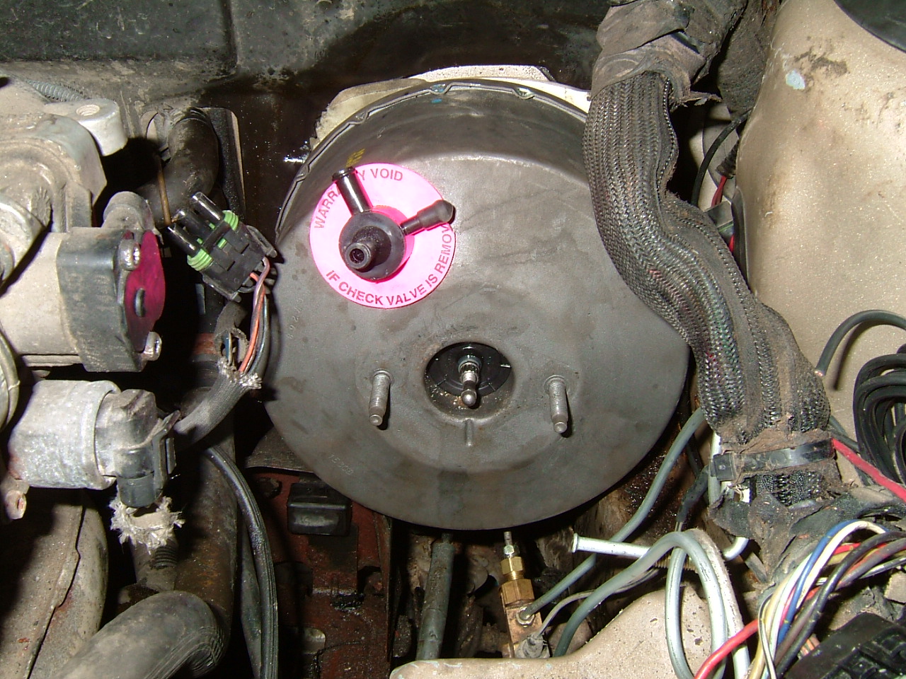
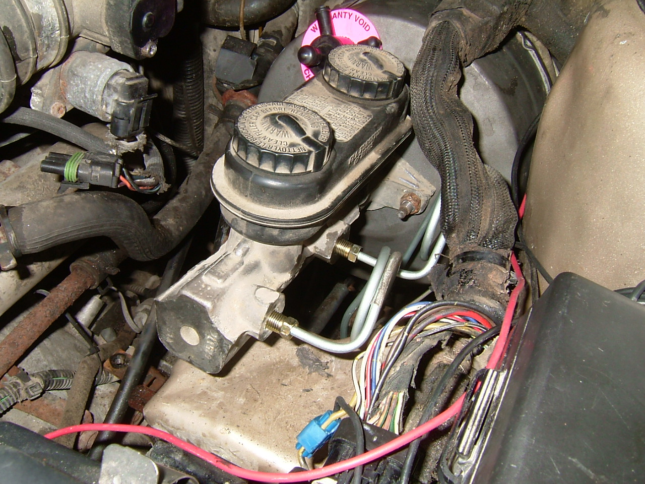
Here you can see the four nuts that hold the ABS master cylinder in and that WILL hold the vacuum booster to the firewall. Note that I've also removed the brake light switch. It just pulls out toward the rear of the car. These pictures were taken after the pedal was removed and the vacuum booster installed. The pedal has a long pin that has a 15mm nut on the inboard end. The outboard end is round but has two flat spots that are perfect for a 7/16" wrench (or a pair of vice grips as I found out).

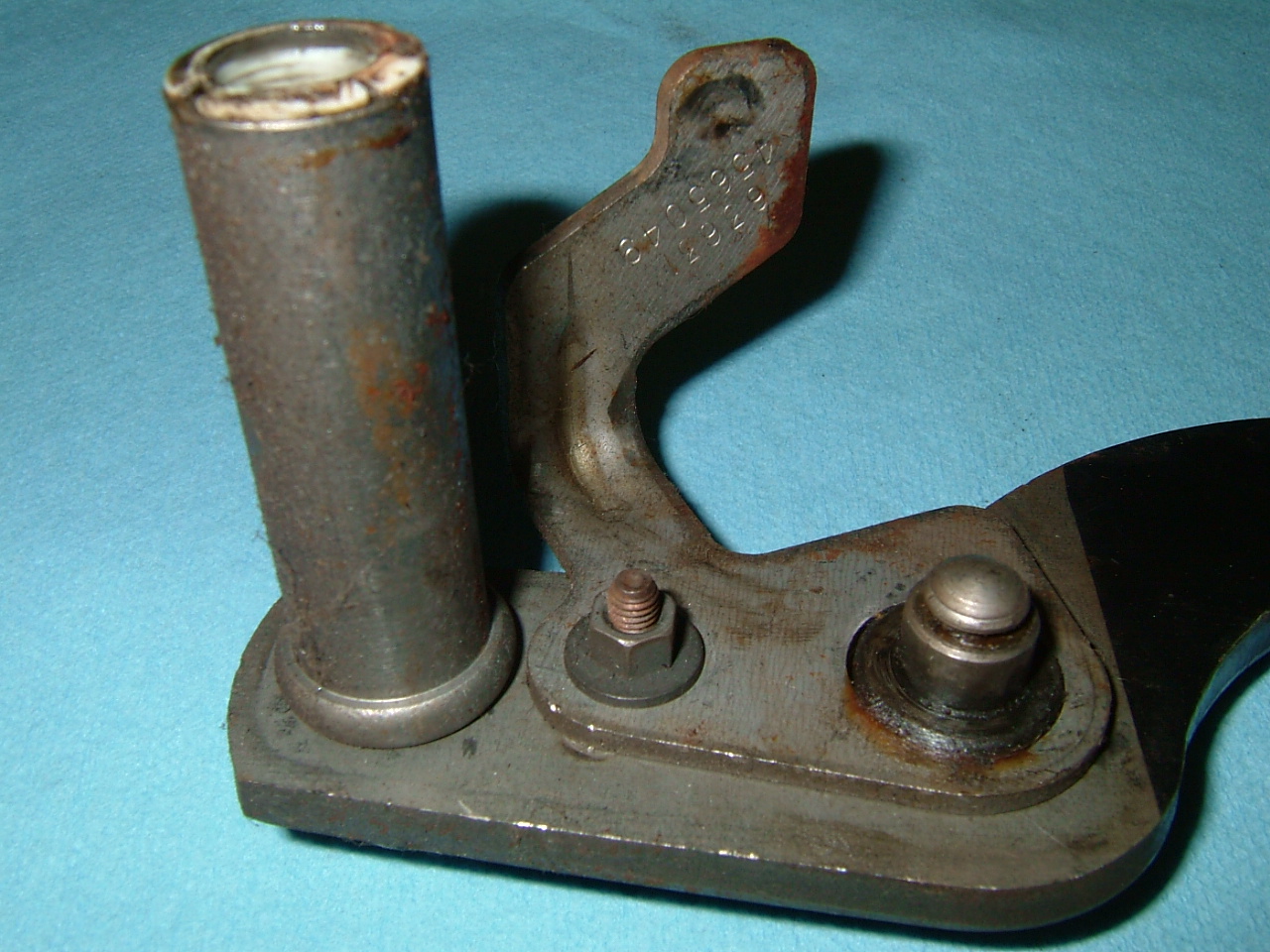
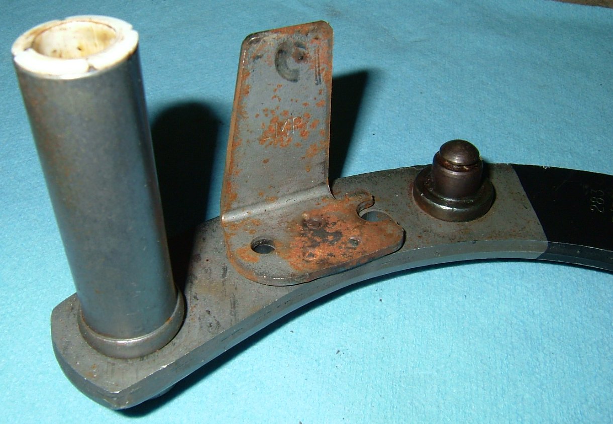
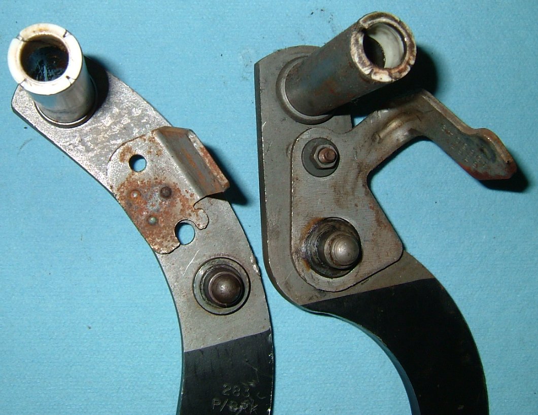
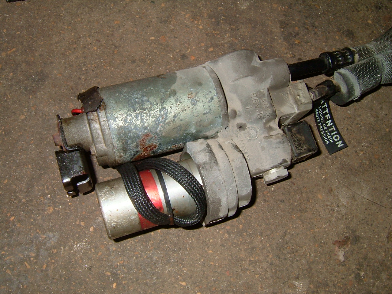
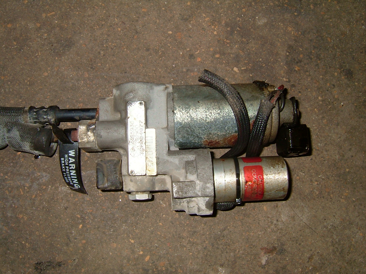
Here you can see why you have to change the brake pedal. Rather than make the master cylinders the same, Chrysler opted to make them different and make different pedal lever assemblies. You can see that the ABS master cylinder shaft is located higher in relation to the four mounting studs and the shaft itself is somewhat longer. The vacuum booster's shaft is located in the center of the four mounting studs and the shaft is shorter. When you change the pedal out, be sure to swap over the nice chrome metal trim from your Imperial pedal to the Dynasty pedal.
| ABS Master Cylinder | Non-ABS Brake Booster |
 |
 |
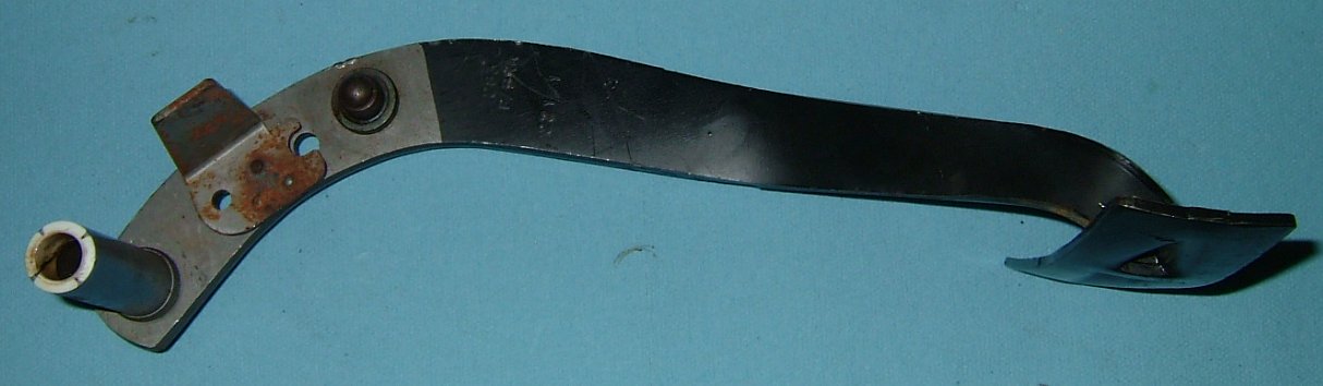
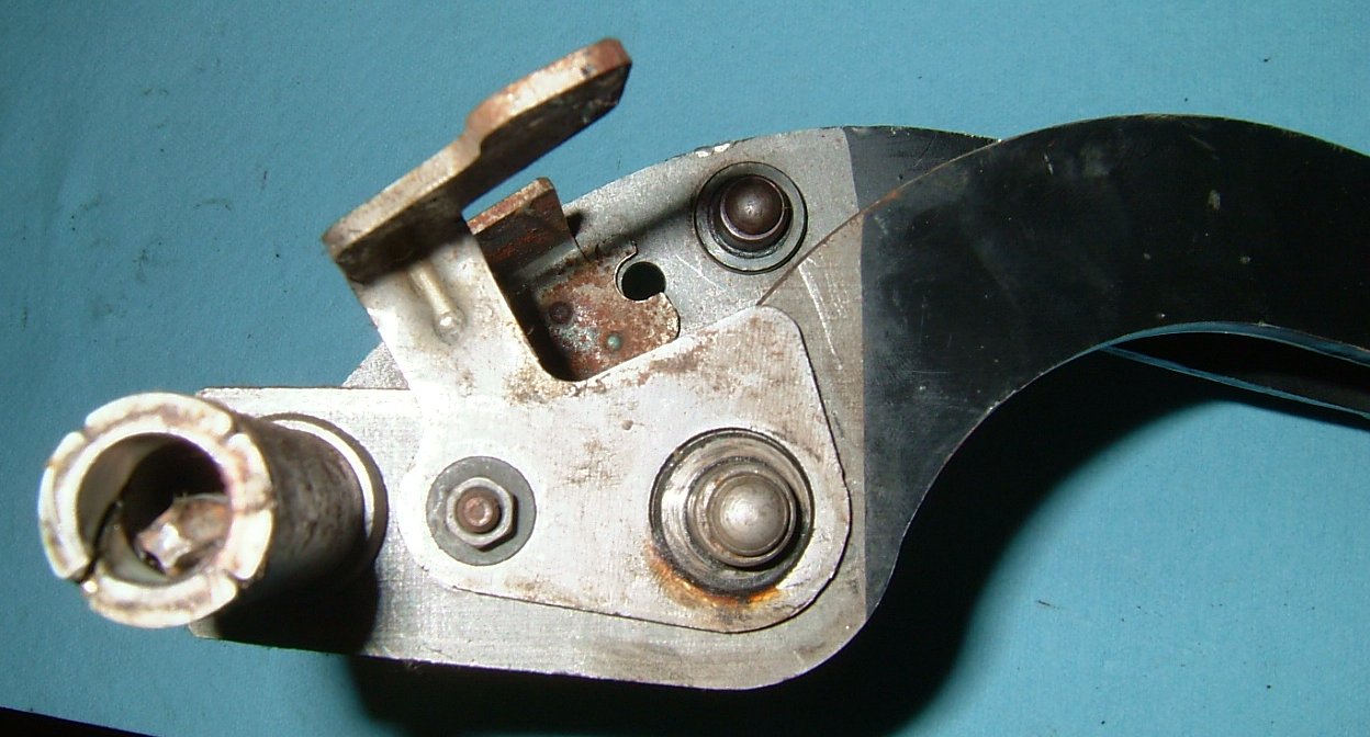
ABS Brake Pedal |
||
 |
 |
 |
Non-ABS Brake Pedal |
||
 |
 |
 |
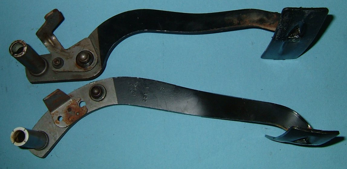
Side by Side |
|||
 |
 |
 |
 |


Remove the four nuts from the master cylinder's mounting studs and remove the clip that holds the rod to the pedal arm. You can now remove the pedal and start wrestling with the huge master cylinder under the hood. Remove all the electrical connectors and four brake lines from the master cylinder. The brake lines are difficult to access and rarely come undone without twisting off the brake line. Just get a good side cutter and cut the brake lines within a couple inches of the master cylinder. You'll have to cut more off them later anyway to make them mate up to the new proportioning valve.
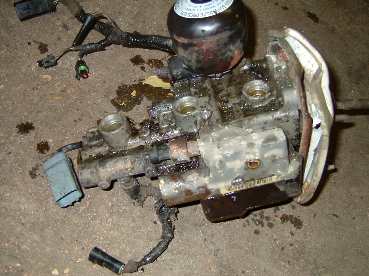
With the master cylinder out, remove the ABS pump. There is only one small bolt holding the pump in. This bolt also holds the pump's cover on so once you remove it, both will come free. You won't need the hoses going to the pump so cut them off.
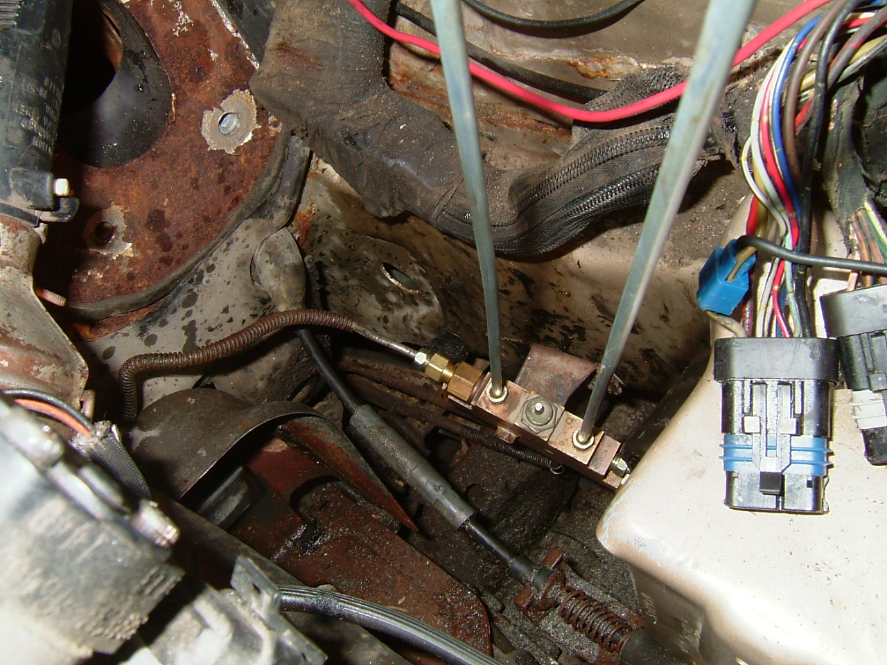
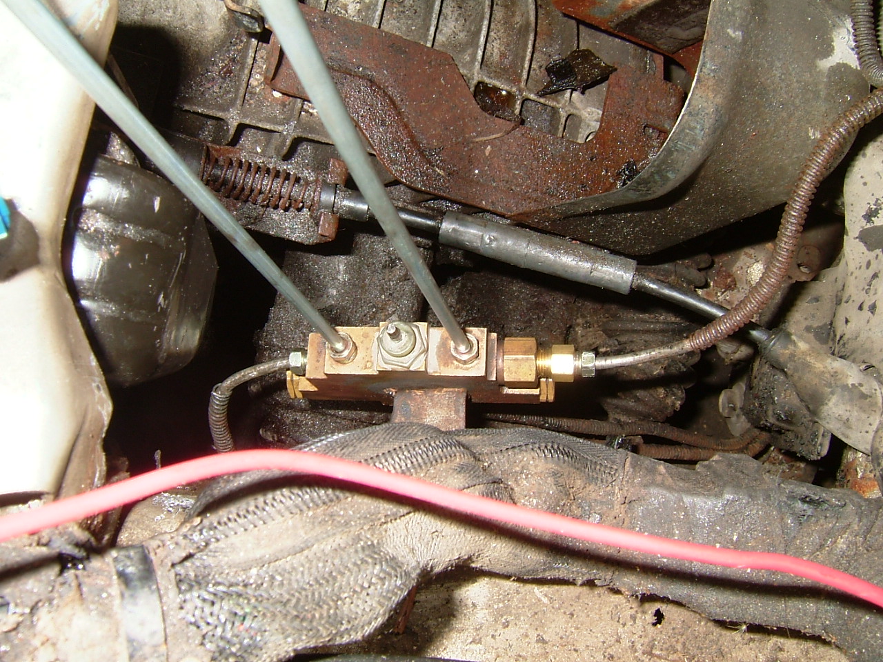
The ABS does not use an external proportioning valve but rather controls all that in the ABS master cylinder itself. I've found that you can't buy proportioning valves from the parts store. You can probably get them at the dealer but they would no doubt be very expensive. The salvage yard where I got the master cylinder and reservoir threw in the proportioning valve. I got the whole assembly for $15. I think just about any K car proportioning valve will do. Mine came from an earlier K car but I think it will be fine. I have yet to test the system so I have yet to confirm this. I had to buy a couple fittings to adapt two of the proportioning valve ports to the 3/16" brake lines. I also bought a flaring tool and some fittings so I could make the Imperial's brake lines fit directly into the proportioning valve. Get the little bracket that the valve mounts on, you can use that on the Imperial.

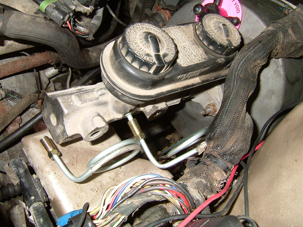
Once I had the brake lines flared, I screwed each one into the proportioning valve and mounted the valve to the frame rail of the car just where it came from off the donor car. I left off the two lines going to the master cylinder for time being (although they are pictured here).
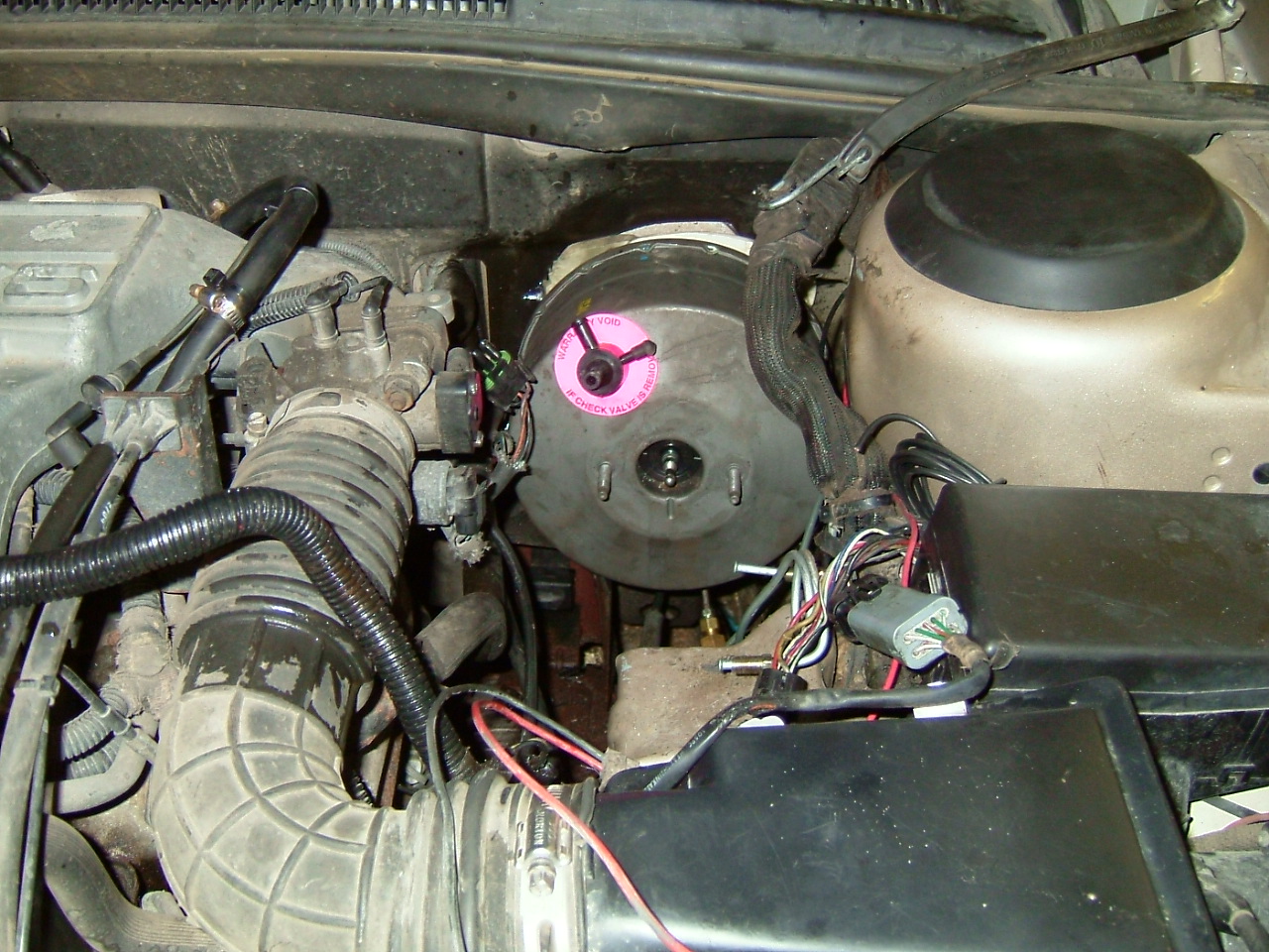
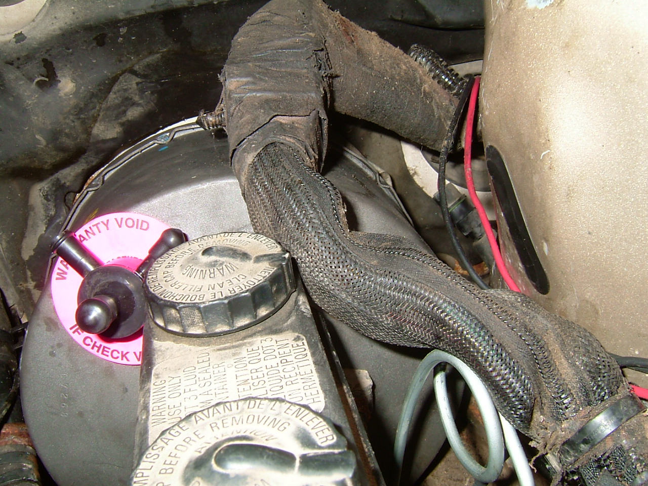
Next was to install the booster. It is a tight fit to get the booster between the strut tower and the engine's intake system but it can be done. I had to lift a section of large wiring harness so the booster would sit tight against the firewall. I put the white foam gasket back in between the booster and the firewall. I had to cut it a little due to the offset hole that was made for the ABS master cylinder. Push the booster's mounting studs through the firewall and thread the retaining nuts onto the studs from inside the car. This can be tricky to line up but it can be done.
Install the replacement brake pedal arm. Slide the pin through the bracket and arm from the outboard side and thread the 15mm nut onto it. Tighten it up good. Slip the eye of the vacuum booster's control shaft over the pin on the brake pedal and install the retaining clip.
You can now connect the vacuum line to the manifold. Use fuel line for this because it is essentially part of the fuel system being that it is connected to the intake manifold. There is a small vacuum line already connected to this port but that line will be moved to the vacuum booster in turn. This small vacuum line is for the climate control system.
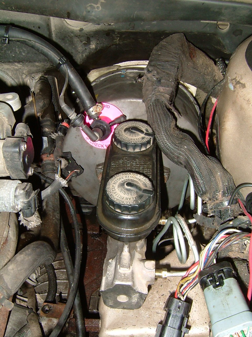
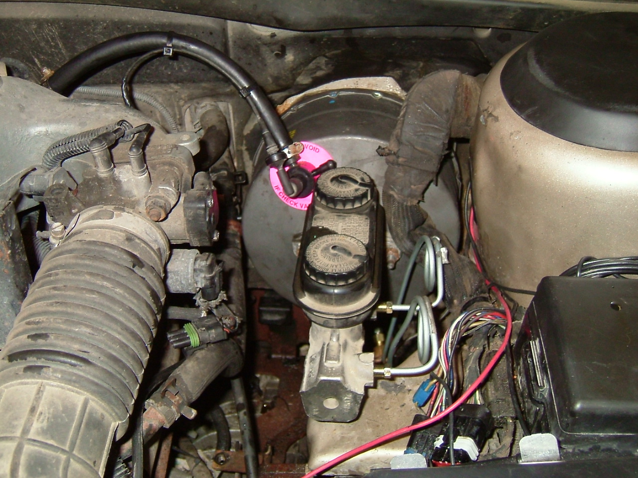
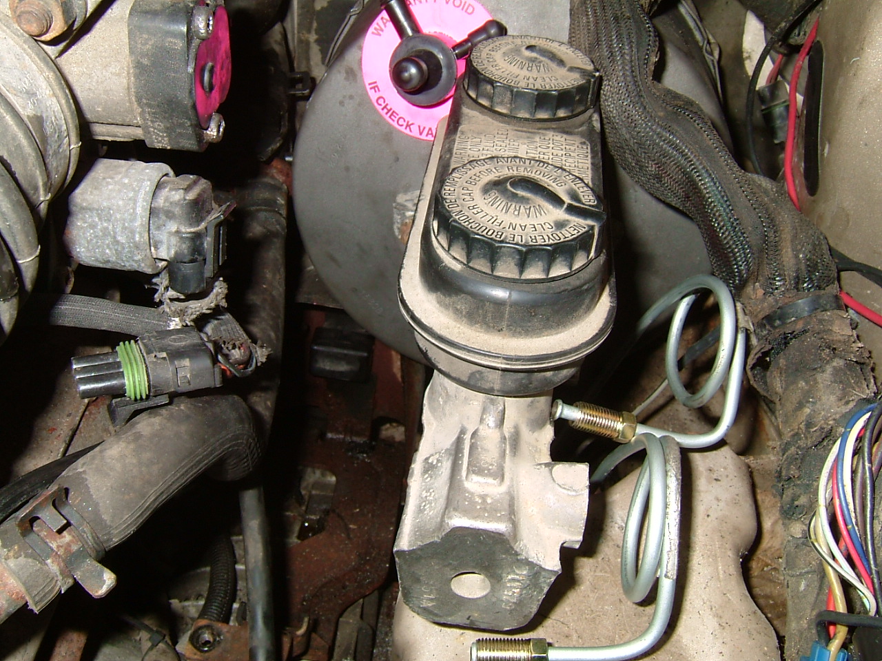
Next, I test fitted the new master cylinder. I used this test fit to position and bend the new brake lines I bought to go from the master cylinder to the proportioning valve. When I had them bent in an appropriate way, I took the master cylinder out again and attached the brake lines to the proportioning valve. I also connected the electrical sensor wire to the proportioning valve and coiled up the lead wire for future connection to the appropriate circuit. When the lines were bent in the proper shape, I reinstalled the master cylinder, installed the two retaining nuts and screwed the two brake lines into the master cylinder.

At this point, bleed the brakes and test for leaks, particularly at the fittings that were hand made with the flaring tool.
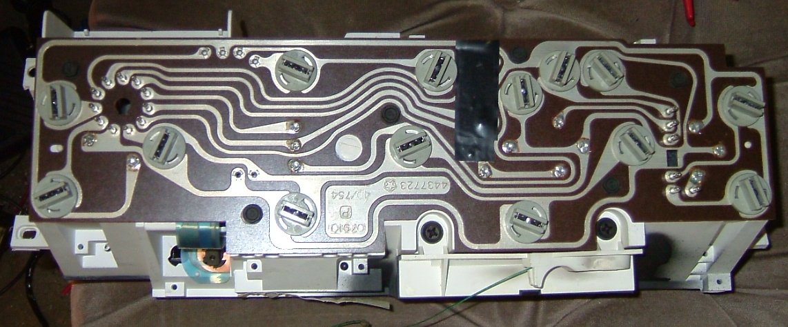
You'll also want to remove the ABS warning light from the instrument cluster. You can see where I have removed it and covered the opening with black electrical tape. This picture shows the back of the instrument cluster. You can be sure you have the right one if after you remove the bulb, shine a light into the opening and you should see the words "ANTI LOCK" light up.
If you notice the pedal doesn't feel right, the brakes apply too early or too late when depressing the pedal, adjust the front end of the booster rod. A turn or two on this adjustment makes a big difference on the pedal so only go one or two turns either way when adjusting. You shouldn't have to remove the brake lines from the master cylinder to do this because although you have to remove the master cylinder from the booster, if you've coiled the lines similar to the way I did, there will be plenty of play in them so you can swing the master cylinder out of the way in order to adjust the booster rod. To make the brakes apply higher on the pedal, turn the rod out or counter clockwise. To make the brakes apply lower on the pedal, turn the rod in or clockwise. You'll have to steady the rod with locking pliers so you can adjust it. I used needle nose locking pliers and a 7mm wrench to perform this adjustment.